ESRI’s ArcGIS Explorer (AGX) is a free GIS viewer which allows the user to view a wide variety of spatial data in both 2D and 3D (globe) display modes. We’ve been working with the latest version, 900, since it was in Beta, and have been impressed with its new Software Development Kit (SDK) and presentation capabilities.
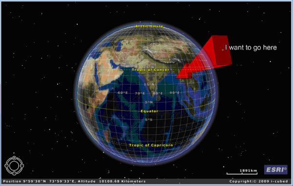
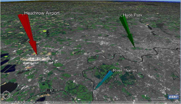
To help us get to grips with AGX 900 we decided to try and create a presentation recounting the exploration history of the North Sea. This took us down some unexpected avenues, and enabled us to take a closer look at the SDK. This blog discusses one of our diversions, which led us to develop a tool that enables the user to create (in big wavy letters) enormous 3D arrows in the sky (you can download our tool at the end of this posting).

We wanted to highlight an area in our AGX presentation, but we didn’t want to use a note icon as they are of a constant size. No, we wanted to do something more complicated and time-consuming. We thought about it for a while and determined that YES, 3D arrows were definitely what was required. So, where to start?
Creating a simple flat vertical arrow
It occurred to us that creating a KML file containing the arrow would be the best thing to do, as we knew a little about creating KML. We’ve subsequently observed that we could probably do it using AGX graphics, but if we wanted to transfer these to another package, we’d have to write them to an interchange format anyway, so KML turned out to be a good choice.
We first worked out how to create a single flat arrow pointing vertically downwards at a target location on the planet. We did this using a template-created ArcGIS Explorer button, using VB.NET code, which we wrote in Visual Studio 2008 Professional (you could use a free Visual Studio Express edition if you don’t have the Professional or higher version). The prototype code worked, but what we really wanted was a 3D arrow which we could easily define the location of, and generate in a repeatable fashion.
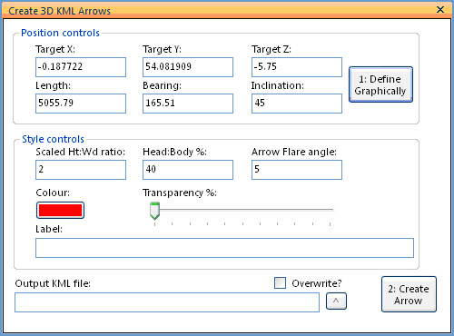
Creating an Arrow Creation tool dialog
AGX’s SDK gives us the ability to create dockable Windows, which can contain a variety of controls. We created one, using the DockWindow template that comes with the SDK. We added some controls, including a button that executes the TrackVector method of the MapDisplay class, which allows the user to define a vector (a polyline with two points) by clicking at two points on the map, the second of which is the target location for the arrow. This vector is then processed to retrieve the bearing and length information to use for the arrow, and all this information is inserted into the controls of the dockable window. We then added some additional controls to allow the style of the arrow to be controlled (to an extent).

Rotating the arrow in 3 dimensions
We now had the tools to repeatedly and easily create the raw parameter data that we required, so it was on to the main challenge, that of actually creating a 3D arrow. We thought for a while and then looked at the AGX SDK developer help. The Rotate method of the GeometryOperations class looked like it could help us with the main problem, that of rotating our vertical arrow in both the horizontal and the vertical planes, if we indulged in a little light trickery. The Rotate method rotates XYZ coordinates around a rotation axis created by extending the supplied rotation point in the Z-dimension. This means that all the Z-values remain the same.
The horizontal (XY) rotation for the arrow was easy, we just needed to process all of the points in our arrow using the Rotate method to rotate them by the specified angle around the target point. But for the other axes, we had to translate the XYZ coordinates before they could be rotated using the Rotate method.
Projecting the arrow coordinates
The target coordinate (XY) was captured in Lat-Longs, and the arrow length/height (Z) defined in metres, so any translation of these values first required us to convert all coordinate values to the same units (preferably metres). Fortunately AGX’s SDK comes with coordinate conversion capabilities. All we needed to do was work out a suitable coordinate reference system (CRS), with units in metres, then transform the source points for our arrow into this CRS. We decided that we’d work out the appropriate UTM zone for the end point and use that (further consideration indicated that we needed to tweak this to use polar CRSs for latitudes above +80 and below -80).
Having implemented this code, we moved on to working out the translations required:
- To rotate around the Z axis:
- no translation
- To rotate around the Y axis:
- X → X, Z → Y, 0 → Z
- To rotate around the X-axis:
- Y → X, Z → Y, 0 → Z
Having rotated the values, we translated them back, incorporating the original omitted value:
- For objects rotated around the Z-axis:
- Rotated X → X, Rotated Y → Y, Original Z → Z
- For objects rotated around the Y-axis:
- Rotated X → X, Original Y → Y, Rotated Y → Z
- For objects rotated around the X-axis:
- Original X → X, Rotated X → Y, Rotated Y → Z
Adding some depth
We now had a rotated (in both the horizontal and vertical planes) arrow pointing at a target location, but its still a flat arrow. In order to give it some depth, we simply rotated the arrow by a small angle perpendicularly away from itself, around the target point, and filled in the gaps that had opened with additional polygons. To make it easier, we actually did this at the start of the process, when the arrow was vertical.
Once we’d got all of the processed coordinate sets, we then back-projected them to Latitude-Longitude and exported them to a KML format file, which we can use in any KML-aware software.

So that’s that, we now have a tool that allows us to create enormous 3D arrows from space.
We are working on a few other KML tools and will be blogging about these in the future, so please check back if you’re interested!
Posted by Ross Smail, Head of R&D, Exprodat.


